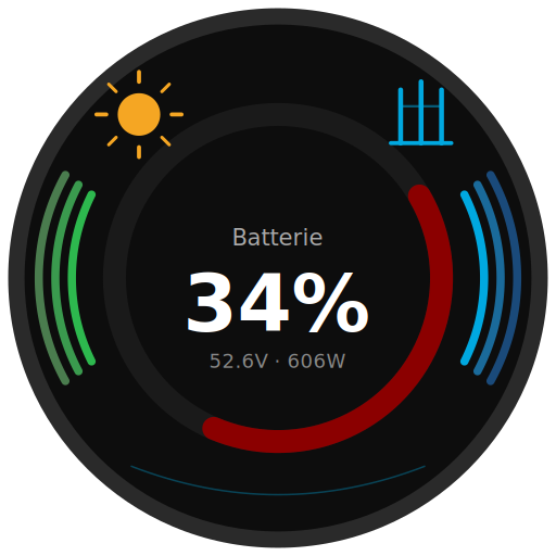
This adapter connects ioBroker directly and locally to Victron Energy GX devices (Cerbo GX, Venus GX, Ekrano GX) – without any detour through Home Assistant or the VRM Cloud.

What does this adapter do?
Connects ioBroker directly and locally to Victron GX devices via the local MQTT protocol. Supports reading all device data and full ESS/inverter control via Modbus TCP.
- All device datapoints are discovered automatically and created as ioBroker states
- Writable datapoints live directly under
devices.*–common.writereflects whether the matching control toggle (Modbus / MQTT) is currently enabled - Works with single-phase and three-phase systems
- Automatic Modbus Unit ID discovery
- Low RAM footprint: ~130 MB stable
- Virtual devices via Node-RED (
dbus-victron-virtual) are fully supported
Requirements
On the GX device:
- Enable MQTT:
Settings → Integrations → MQTT access → On - For Modbus control:
Settings → Integrations → Modbus TCP Server → Enabled - Write access:
Access level → Write access allowed
In ioBroker:
- Node.js >= 22
- Admin >= 7.7.28
Installation
Via ioBroker Admin (recommended)
Since this adapter is not yet in the official ioBroker repository, install it via the npm tab in the Admin interface:
- Open ioBroker Admin
- Go to Adapters
- Click the GitHub/Cat icon (top right)
- Select the npm tab
- Enter
iobroker.victron-gxand click Install
After installation
- Configure the instance:
- Enter IP address of GX device
- MQTT port:
1883(default) - Optional: Modbus control (ESS/inverter registers become writable via Modbus TCP)
- Optional: MQTT control (switches, EV charger, temperature setpoints become writable via MQTT)
Note: Node.js >= 22 is required. If your ioBroker is running on Node.js 20, please update first.
Configuration
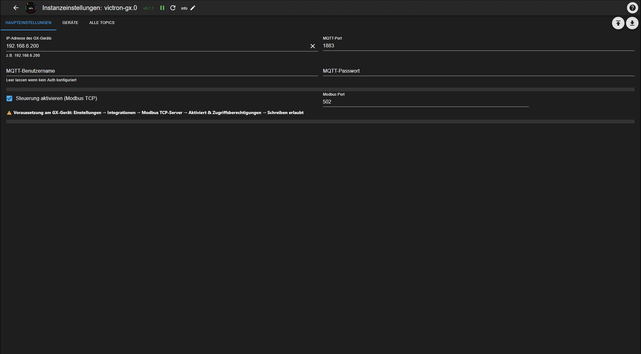
| Field | Description |
|---|---|
| IP address of GX device | Local IP of Cerbo/Venus/Ekrano GX |
| MQTT port | Default: 1883 |
| MQTT username / password | Only if MQTT auth is configured on GX |
| Modbus control | Makes ESS/inverter (vebus, system) datapoints writable via Modbus TCP |
| Modbus port | Default: 502 |
| MQTT control | Makes switches, EV charger and temperature setpoints writable via MQTT |
Supported Devices
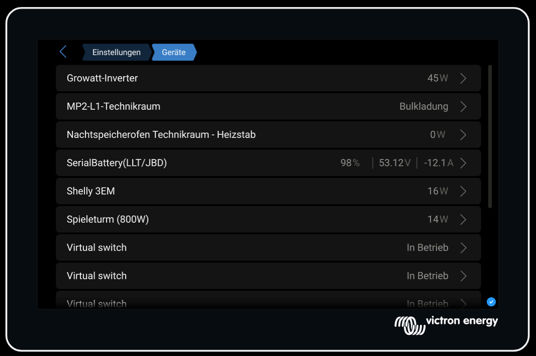
The adapter automatically discovers all devices connected to the GX device:
| Device type | Description |
|---|---|
battery | Battery systems (e.g. SerialBattery/LLT/JBD) |
vebus | MultiPlus/Quattro inverters |
grid | Grid meters (e.g. Shelly 3EM, Carlo Gavazzi) |
pvinverter | PV inverters |
acload | AC loads (incl. Shelly 1PM, with switchable output) |
switch | Switchable outputs (Node-RED virtual switches, Shelly Pro3/Pro4/1PM, GX internal relay) |
evcharger | EV chargers (read + control) |
temperature | Temperature sensors |
meteo | Weather stations |
tank | Tank level sensors |
system | System overview |
Object Structure
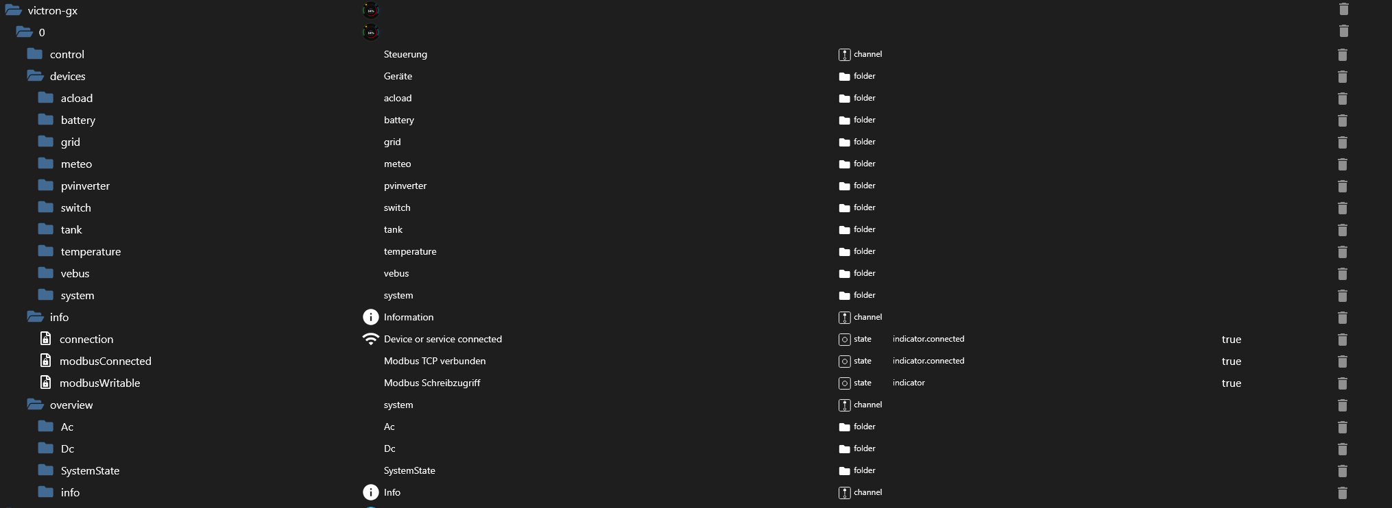
victron-gx.0
├── devices.*          → All discovered devices - common.write on the individual datapoint tells
│   │                     you whether it's currently writable (see "Writable Data Points" below)
│   ├── battery.*
│   ├── vebus.*                      → Mode, Ac.In1.CurrentLimit, Hub4.* writable (Modbus control)
│   ├── grid.*
│   ├── pvinverter.*
│   ├── acload.<Group>.<Serial>.
│   │   ├── Ac.*                     → measurements (unchanged)
│   │   └── outputs.<N>.             → switchable output, if the device has one (e.g. Shelly 1PM)
│   │       ├── State                    bool, writable (MQTT control)
│   │       ├── Status                   bool, read-only
│   │       ├── Name / CustomName        string
│   │       └── Group                    string
│   ├── switch.<Group>.<Serial>.
│   │   └── outputs.<N>.             → one sub-channel per output (Node-RED: one, Shelly Pro3/4: up to four)
│   │       ├── State / Status / Name / CustomName / Group   (same as above)
│   ├── evcharger.<Serial>.          → SetCurrent, StartStop, Mode writable (MQTT control)
│   ├── temperature.<Serial>.        → Offset, Scale, FilterLength writable (MQTT control)
│   ├── meteo.*
│   ├── tank.*
│   └── system.<Serial>.             → GridSetpoint, EssMode, MinimumSoc, ... writable (Modbus control);
│                                       also carries outputs.0.* for the GX internal relay (MQTT control)
├── overview.*         → System overview (from system/0), read-only
└── info.*             → Connection status
<Group> is an optional intermediate folder – only present if a group name is configured for that channel/device. See Shelly Integration & Multi-Channel Support below for details.
Device List (Admin)
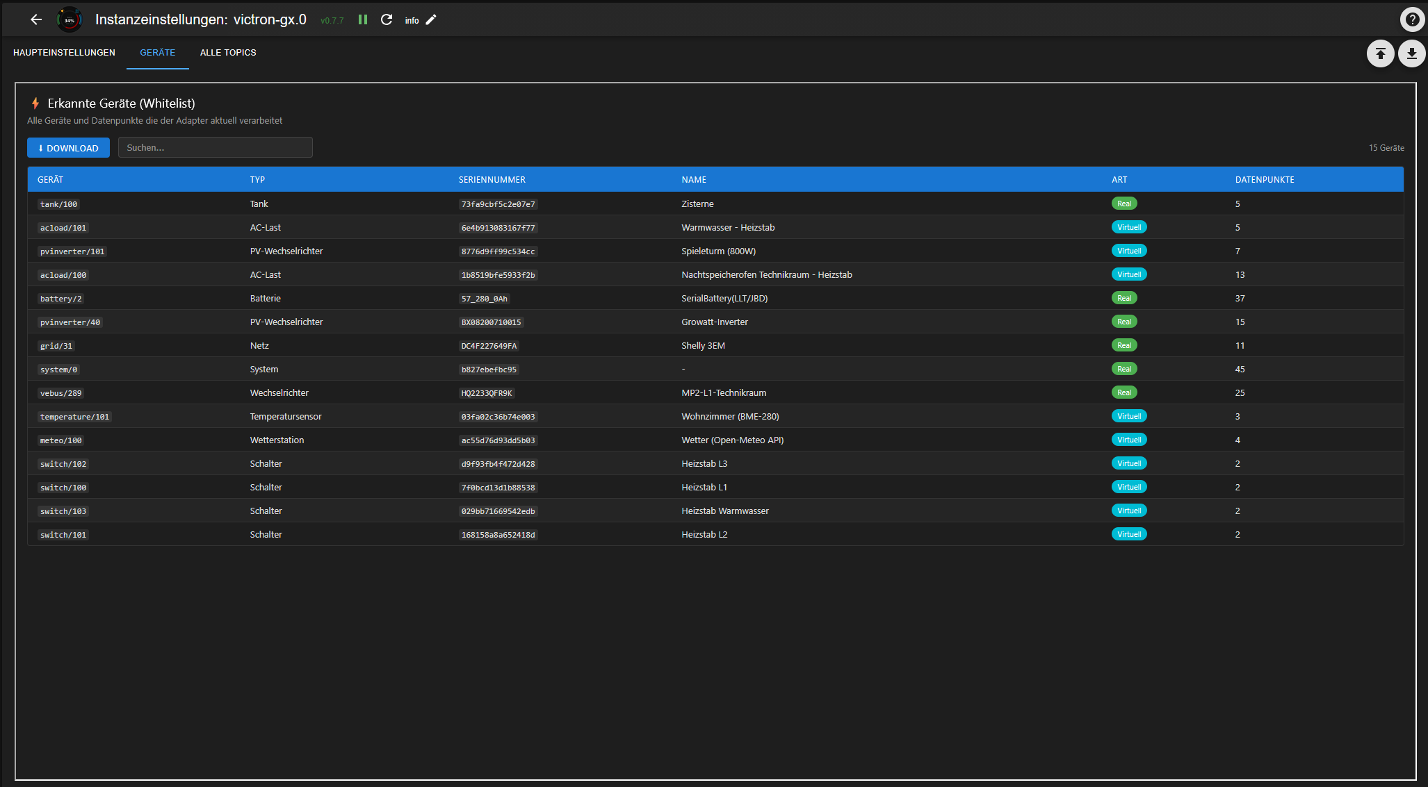
The Devices tab shows all discovered devices with type, serial number, name and number of datapoints. The list can be downloaded as a JSON file – useful for support requests.
Topic Catalog (Admin)
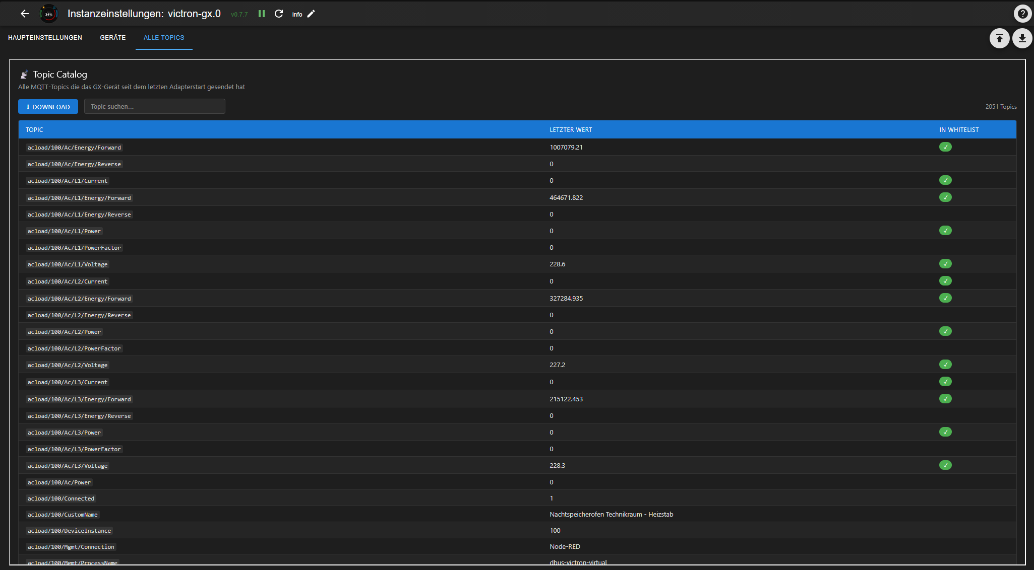
The All Topics tab shows all MQTT topics that the GX device has sent since the last adapter start. Topics processed by the adapter are marked with ✓. The catalog can be downloaded as a JSON file.
Writable Data Points
Since 0.10.0, there is no separate control.* tree anymore. Every writable datapoint lives
directly under devices.*, right next to its read-only siblings – common.write on the object
itself tells you (and the Admin UI / VIS) whether it's currently writable. Two independent config
toggles gate this:
- Modbus control – ESS/inverter registers on
devices.vebus.*anddevices.system.* - MQTT control – switches (
devices.switch.*/devices.acload.*/devices.system.*outputs), the EV charger, and temperature-sensor calibration setpoints
If a toggle is off, the datapoint still exists (so History/Vis bindings and scripts keep working)
but common.write is false and writes are ignored with a log warning – no more silently swallowed
writes to a datapoint that looked writable but wasn't.
Before → after (upgrading from 0.9.x)
| Old (control.*, removed in 0.10.0) | New (devices.*) |
|---|---|
control.inverter.Mode | devices.vebus.<Serial>.Mode |
control.inverter.AcPowerSetpoint | devices.vebus.<Serial>.Hub4.L1.AcPowerSetpoint |
control.inverter.AcIn1CurrentLimit | devices.vebus.<Serial>.Ac.In1.CurrentLimit |
control.inverter.DisableCharge | devices.vebus.<Serial>.Hub4.DisableCharge |
control.inverter.DisableFeedIn | devices.vebus.<Serial>.Hub4.DisableFeedIn |
control.system.GridSetpoint | devices.system.<Serial>.GridSetpoint |
control.system.EssMode | devices.system.<Serial>.EssMode |
control.system.MinimumSoc | devices.system.<Serial>.MinimumSoc |
control.system.BatteryLifeState | devices.system.<Serial>.BatteryLifeState |
control.system.MaxFeedInPower | devices.system.<Serial>.MaxFeedInPower |
control.system.AcFeedInEnabled | devices.system.<Serial>.AcFeedInEnabled |
control.system.DcFeedInEnabled | devices.system.<Serial>.DcFeedInEnabled |
control.system.DvccMaxChargeCurrent | devices.system.<Serial>.DvccMaxChargeCurrent |
control.system.MaxDischargePower | devices.system.<Serial>.MaxDischargePower |
control.evcharger.<Instance>.SetCurrent | devices.evcharger.<Serial>.SetCurrent |
control.evcharger.<Instance>.StartStop | devices.evcharger.<Serial>.StartStop |
control.evcharger.<Instance>.Mode | devices.evcharger.<Serial>.Mode |
What to do: update any scripts, Vis widgets, or Blockly rules that reference control.*
directly, and make sure the matching toggle (Modbus control / MQTT control) is enabled in the
instance settings if you rely on writing to any of these. The adapter renames the config key
controlEnabled to modbusControlEnabled automatically on first 0.10.0 start (your setting is
preserved) – mqttControlEnabled is unchanged. A one-time cleanup removes any leftover control.*
objects, and a warning is logged on every start in 0.10.x/0.11.x as a reminder (removed in 0.12.0).
Switches are now gated too: outputs.<N>.State used to be writable unconditionally; it now
requires MQTT control to be enabled, same as everything else under this toggle.
Examples
ESS Grid Setpoint (simplest approach) – write devices.system.<Serial>.GridSetpoint [W]:
0→ zero feed-in (Victron ESS algorithm keeps grid at 0W)-3000→ feed 3000W into grid (battery discharges)+500→ draw 500W from grid (battery charges)
No keepalive needed – value is stored persistently.
ESS Live Setpoint (direct control) – write devices.vebus.<Serial>.Hub4.L1.AcPowerSetpoint [W]:
- Requires
devices.system.<Serial>.EssMode = 3(External control) - The adapter resends the value every 800ms while it is ≠ 0 (Victron watchdog)
- Set to
0to return control to the Victron ESS algorithm
Disable Charge / Feed-In:
devices.vebus.<Serial>.Hub4.DisableCharge = 1→ battery will not chargedevices.vebus.<Serial>.Hub4.DisableFeedIn = 1→ inverter will not feed into grid
DVCC Limits (requires DVCC enabled on GX):
devices.system.<Serial>.DvccMaxChargeCurrent[A]: system-wide charge current limit (-1 = disabled)devices.system.<Serial>.MaxDischargePower[W]: discharge power limit
Virtual Switches (Node-RED) – set outputs.<N>.State to true/false → MQTT write → GX → Node-RED → relay
EV Charger – write devices.evcharger.<Serial>.SetCurrent [A] / StartStop [bool] / Mode (0=Manual, 1=Auto, 2=Scheduled)
Temperature sensor calibration – write devices.temperature.<Serial>.Offset [°C] / Scale / FilterLength
Virtual Devices (Node-RED)
The adapter fully supports virtual devices created via Node-RED with the dbus-victron-virtual package:
- Virtual PV inverters
- Virtual AC loads
- Virtual switches (with group and individual name)
- Virtual temperature sensors
- Virtual weather stations
- Virtual tank sensors
Shelly Integration & Multi-Channel Support
Shelly devices connected to the GX (Cerbo/Venus/Ekrano) integration are now fully supported, alongside Node-RED virtual switches:
- Shelly Pro3 / Pro4: each physical device reports its channels as separate MQTT device instances that share the same serial number. The adapter automatically merges them into a single object tree (
devices.switch.<Group>.<Serial>.outputs.<0..3>.*). - Shelly 1PM: measurement values (
Ac.*) and the switchable output (outputs.0.*) live on the same device tree underdevices.acload.<Group>.<Serial>. - GX internal relay: the relay built into the GX device itself (
system/0) is switchable underdevices.system.<Serial>.outputs.0.State, once MQTT control is enabled (see Writable Data Points).
All switchable outputs – regardless of device type – share the same sub-structure, so wildcard selectors work across your whole installation:
// Every switchable output, any device type, any group
'victron-gx.0.devices.*.*.*.outputs.*.State'

// Just the custom names, for a device overview
'victron-gx.0.devices.*.*.*.outputs.*.CustomName'
⚠️ Breaking change (v0.9.x)
Switch outputs used to live directly under the device channel; they now live under an outputs.<N> sub-channel. Node-RED's output_1 is normalized to outputs.1:
| Old (v0.8.x) | New (v0.9.x) |
|---|---|
devices.switch.<Group>.<Serial>.State | devices.switch.<Group>.<Serial>.outputs.1.State |
devices.switch.<Group>.<Serial>.Status | devices.switch.<Group>.<Serial>.outputs.1.Status |
Update any scripts, Vis widgets, or Blockly rules that reference the old paths directly.
If you want to remove the leftover old objects, run this in the ioBroker CLI (the trailing loop works around the known "Invalid ID: undefined" error when deleting via the Admin UI):
iobroker object list | grep -oP 'victron-gx\.0\.devices\.switch\.[^.]+\.[^.]+\.(State|Status)